It’s a sign…
It’s a sign…
Here we have programmed a Raspberry Pi board using Python to make is act as a WiFi server for the FlowPaw board (i.e. to make it wireless). This means that you can write your own program to control the FlowPaw using FlowStone on the PC (or even your browser using HTTP) live whilst having wireless control using your standard home network!

No more downloading code into a chip (Aka Lego Mindstorms) or struggling programming the Raspberry Pi, do it live on screen in FlowStone and save time!
All you need is a Raspberry Pi with a WiFi dongle, setup to run our pre-made Python script which runs each time you boot it. So you don’t even need to connect a keyboard, screen or mouse to your Pi. The Pi then connects to the FlowPaw board via USB and you’re off.
In this case we are using an Xbox games controller connected to the PC in FlowStone to drive the rover around. Add a few proximity sensors and you will have an autonomous rover with the code running via telemetry on the PC – how cool is that!
Whist the FlowPaw is mainly designed to work with the FlowStone STEM software making programming really quick and easy, for those of you out there that would like to use Python on the Raspberry Pi this is also possible too!
Here is our first working test of the Rpi sending data to the FlowPaw board as a stand alone system.
With just a little more Python we have the Buzzer Claw and Scrolling Text working on the FlowPaw board with Rpi:
Ben testing the new FlowPaw board & FlowStone STEM:
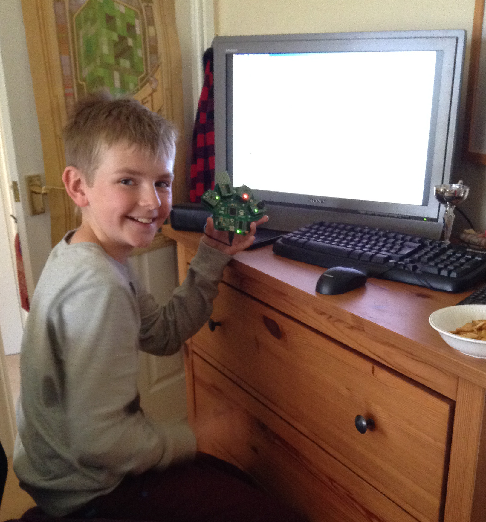
We gave Ben (Age 12) a FlowPaw and FlowStone STEM to play with, after playing with the demo projects he was off creating within an hour..
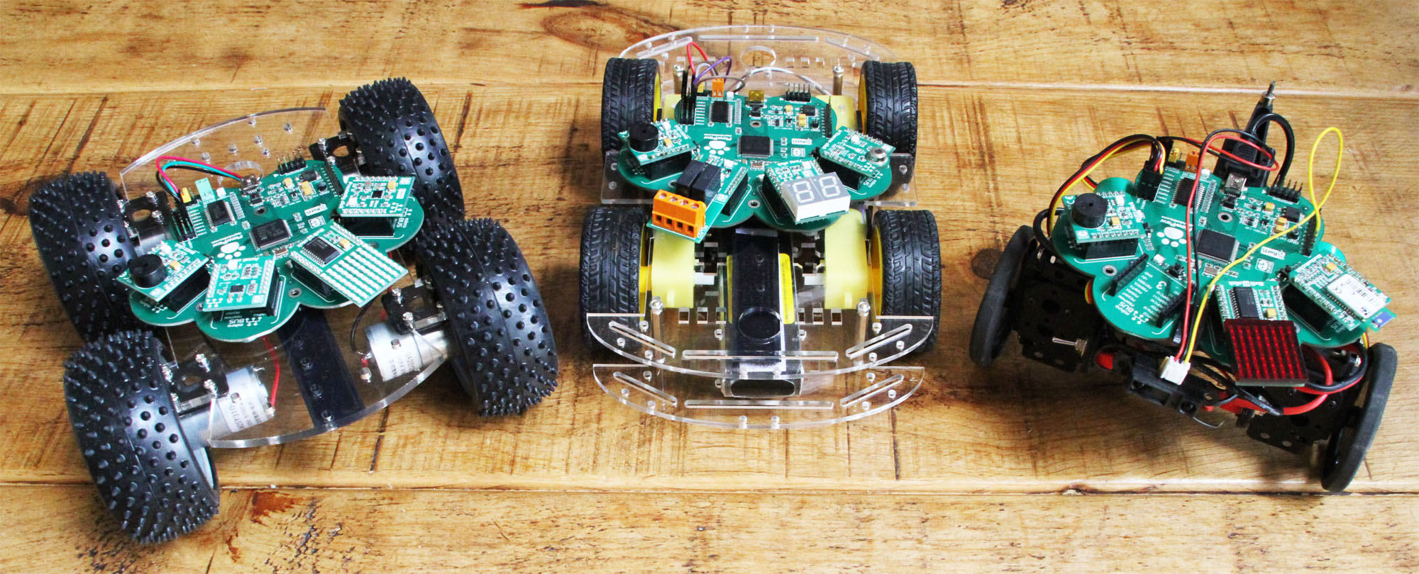
Today we tested several rover chassis for the FlowPaw rover kit:
See how we got on… Continue reading
The FlowPaw goes wireless using the Bluetooth Claw!
Here we are using a LynxMotion Rover controlled from two servo outputs on the FlowPaw board and some Infrared distances sensors to detect objects.
All of the decisions and control are coming from the PC using the FlowStone STEM programming language.
The samples of the new packaging have arrived – how exciting:
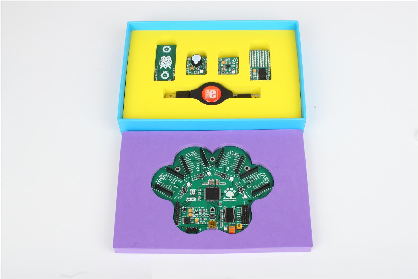
Also in the box will be a CD with the FlowStone STEM software and Example files etc. Plus a quick start guide etc.
FlowPaw is working really well now so we thought we would make a in depth video showing you how it works with FlowStone and how easy it is to program:
So after a few days of low-level programming the Firmware for the FlowPaw board we finally have it working working with FlowStone!
Here a little video:
Here’s the FlowPaw Rev0 with four Claws fitted!
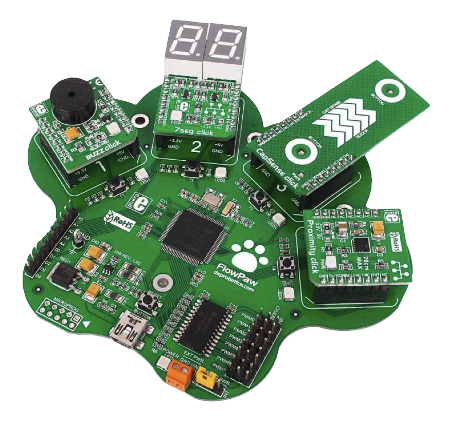
In this case a buzzer, a LED display, a capacitive touch sensor and an infrared proximity sensor.
The board spec was:
The design was worked out with MikroElektonika and within a matter of weeks the first prototype boards were on our desk!