Consider the analog non-inverting amp schematic below.
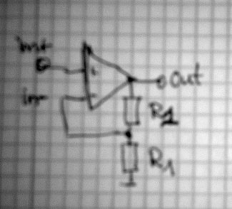
- IMG_1457.JPG (26.66 KiB) Viewed 34826 times
The system behavior is determined by the op amp free running gain and the feedback topology. Thus, the op amp output is given by
where in+ is the voltage at the non-inverting input and in- is the voltage at the inverting input. The latter receives a fraction k = R1/(R1 + R2) of the output voltage,
Substituting this expression in the first equation we obtain
What happens if we apply some nonzero voltage to the non-inverting input? The output will respond immediately, however since a fraction of the output is fed back to the inverting input, the response will not be with the full free running gaing. We can actually compute the resulting loop gain by solving for out,
Code: Select all
out = gain*in+/(1 + gain*k) = in+/k
the second equality being a high-gain approximation.
Now what happens in the digital domain? A naive code would look like this:
Code: Select all
streamin in;
streamin k;
streamout out;
float gain=1000;
out = gain*(in - k*out);
Let's analyze step by step what happens if we apply an input signal, say in = 0.1. For the sake of simplicity, assume R1 = R2 or k = 0.5. From the analog circuit we woult expect roughly out = 0.2.
Let us assume that before we applied the input signal, the output was zero. In the first step the right hand side of the assignment instruction evaluates to
gain*(in - k*out) = 1000*(0.1 - 0.5*0) = 100
So at the end of step 1, out = 100.
In the second step, the right hand side evaluates to
gain*(in - k*out) = 1000*(0.1 - 0.5*100) = 100 - 50000 = -49900.
So at the end of step 2, out = -49900! You can easily work out further steps and see that the system blows up exponentially instead of reaching the value out = 0.2. The trouble is that in the assignment instruction, the variable out on the right hand side is different from the variable on the left hand side, the difference being a unit delay.